Hello,
I have resistivity measurement project using 2 DMMs,one for measuring V and the other for I.
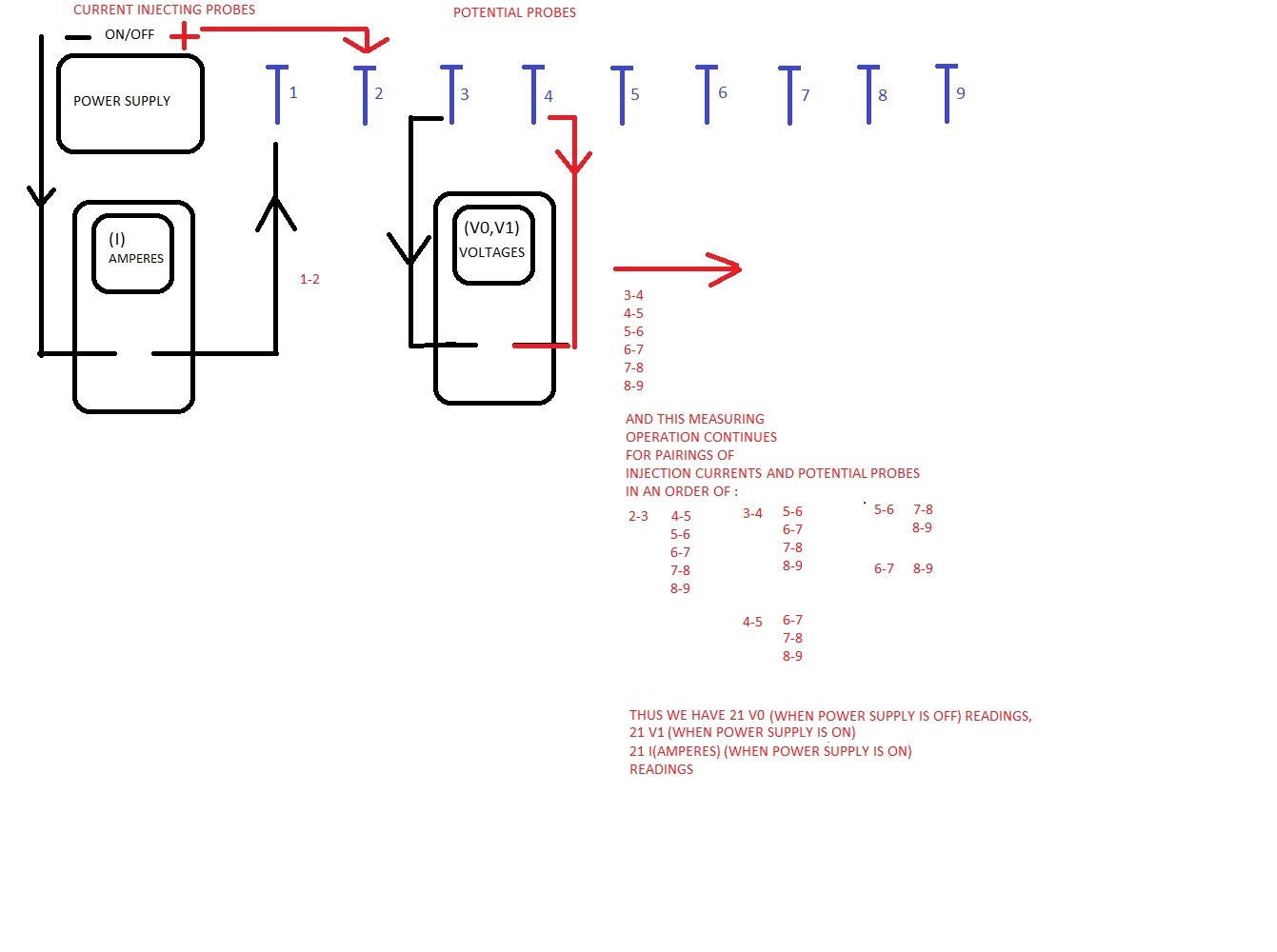
Since I prefer to apply dipole-dipole method,I designed a measurement cable connected to 9 probes,in order to stop the measurement at the n6 stage.Thus I read the injected current from the first 2 probes,and I read the potentials from the following probes(C1-C2;P1-P2).Firstly I take the potential readings from P1-P2 as power supply is turned-off.Then I turn on the power supply and I take current readings from C1-C2 and voltage readings from P1-P2.This is repeated for each pairings as told in the figure attached.
|C1|C2||P1|P2|
|1|2| |3|4|
|1|2| |4|5|
|1|2| |5|6|
|1|2| |6|7|
|1|2| |7|8|
|1|2| |8|9|
|2|3| |4|5|
|2|3| |5|6|
|2|3| |6|7|
|2|3| |7|8|
|2|3| |8|9|
|3|4| |5|6|
|3|4| |6|7|
|3|4| |7|8|
|3|4| |8|9|
|4|5| |6|7|
|4|5| |7|8|
|4|5| |8|9|
|5|6| |7|8|
|5|6| |8|9|
|6|7| |8|9|
Finally I have 21 V0,21 V1 and 21 I readings,as a total of 63 readings.
Is it possible to design and apply this switching with esp32 and MUX?And is it possible to record the savings afterall?(The model of DMMs I used is General Tools TS04,which has bluetooth).